
Locking Assemblies RfN 7014
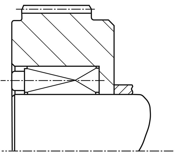
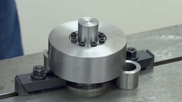
This locking device, dual tapered similar the 7012 type, is designed to transmit extremely high torques. Unlike the 7012 style, the 7014 device offers good centering ability due to it’s relatively long design, making a pre-centering hub section unnecessary. It’s design also provides for a different inside diameter to outside diameter ration, thereby not interchangeable with the other RINGFEDER® types. Available in sizes from 70 to 300 mm.
Technical Data & CAD Models
| CAD |
d
mm |
D
mm |
L
mm |
L1
mm |
L3
mm |
T
Nm |
pW
N/mm2 |
pN
N/mm2 |
DG
mm |
TA
Nm |
DN min bei Rp0,2 400 N/mm2
mm |
Tmax
Nm |
|---|---|---|---|---|---|---|---|---|---|---|---|---|
| 60 | 100 | 60 | 50 | 44 | 4130 | 208 | 125 | 10 | 84 | 139 | 5120 | |
| 70 | 120 | 74 | 62 | 56 | 6850 | 200 | 117 | 12 | 145 | 154 | 8068 | |
| 80 | 130 | 74 | 62 | 56 | 11650 | 263 | 162 | 12 | 145 | 189 | 13813 | |
| 90 | 140 | 74 | 62 | 56 | 13000 | 234 | 150 | 12 | 145 | 196 | 15505 | |
| 100 | 160 | 94 | 80 | 74 | 19700 | 213 | 133 | 14 | 230 | 217 | 23620 | |
| 110 | 170 | 94 | 80 | 74 | 26600 | 242 | 157 | 14 | 230 | 248 | 32045 | |
| 120 | 180 | 94 | 80 | 74 | 28900 | 222 | 148 | 14 | 230 | 255 | 34968 | |
| 130 | 190 | 94 | 80 | 74 | 31200 | 205 | 140 | 14 | 230 | 263 | 37903 | |
| 140 | 200 | 94 | 80 | 74 | 40200 | 227 | 159 | 14 | 230 | 294 | 49017 | |
| 150 | 210 | 94 | 80 | 74 | 42900 | 212 | 151 | 14 | 230 | 301 | 52489 | |
| 160 | 230 | 110 | 94 | 88 | 64000 | 227 | 158 | 16 | 355 | 339 | 78558 | |
| 170 | 240 | 110 | 94 | 88 | 67800 | 214 | 152 | 16 | 355 | 347 | 83477 | |
| 180 | 250 | 110 | 94 | 88 | 83000 | 235 | 169 | 16 | 355 | 384 | 102483 | |
| 190 | 260 | 110 | 94 | 88 | 88000 | 223 | 163 | 16 | 355 | 390 | 108947 | |
| 200 | 270 | 110 | 94 | 88 | 105000 | 242 | 179 | 16 | 355 | 431 | 130330 | |
| 220 | 300 | 134 | 116 | 110 | 123000 | 189 | 139 | 18 | 485 | 420 | 153404 | |
| 240 | 320 | 134 | 116 | 110 | 153000 | 198 | 148 | 18 | 485 | 463 | 191651 | |
| 260 | 340 | 134 | 116 | 110 | 186000 | 205 | 157 | 18 | 485 | 506 | 233920 | |
| 280 | 370 | 156 | 136 | 130 | 230000 | 192 | 145 | 20 | 690 | 533 | 290328 | |
| 300 | 390 | 156 | 136 | 130 | 245000 | 179 | 138 | 20 | 690 | 548 | 310335 |
| CAD |
d inch |
D inch |
L inch |
L1 inch |
L3 inch |
T ft-lbs |
pW psi |
pN psi |
DG mm |
TA ft-lbs |
DN min bei Rp0,2 400 N/mm2 inch |
Tmax ft-lbs |
|---|---|---|---|---|---|---|---|---|---|---|---|---|
| 2.362 | 3.937 | 2.362 | 1.969 | 1.732 | 3046 | 30190 | 18143 | M 10 | 62 | 5.472 | 3776 | |
| 2.756 | 4.724 | 2.913 | 2.441 | 2.205 | 5052 | 28986 | 16957 | M 12 | 107 | 6.063 | 5951 | |
| 3.150 | 5.118 | 2.913 | 2.441 | 2.205 | 8593 | 38116 | 23478 | M 12 | 107 | 7.441 | 10188 | |
| 3.543 | 5.512 | 2.913 | 2.441 | 2.205 | 9588 | 33913 | 21739 | M 12 | 107 | 7.717 | 11436 | |
| 3.937 | 6.299 | 3.701 | 3.150 | 2.913 | 14530 | 30870 | 19275 | M 14 | 170 | 8.543 | 17421 | |
| 4.331 | 6.693 | 3.701 | 3.150 | 2.913 | 19619 | 35072 | 22754 | M 14 | 170 | 9.764 | 23635 | |
| 4.724 | 7.087 | 3.701 | 3.150 | 2.913 | 21316 | 32174 | 21449 | M 14 | 170 | 10.039 | 25791 | |
| 5.118 | 7.480 | 3.701 | 3.150 | 2.913 | 23012 | 29710 | 20290 | M 14 | 170 | 10.354 | 27956 | |
| 5.512 | 7.874 | 3.701 | 3.150 | 2.913 | 29650 | 32899 | 23043 | M 14 | 170 | 11.575 | 36154 | |
| 5.906 | 8.268 | 3.701 | 3.150 | 2.913 | 31642 | 30725 | 21884 | M 14 | 170 | 11.850 | 38714 | |
| 6.299 | 9.055 | 4.331 | 3.701 | 3.465 | 47205 | 32899 | 22899 | M 16 | 262 | 13.346 | 57942 | |
| 6.693 | 9.449 | 4.331 | 3.701 | 3.465 | 50007 | 31014 | 22029 | M 16 | 262 | 13.661 | 61570 | |
| 7.087 | 9.843 | 4.331 | 3.701 | 3.465 | 61218 | 34058 | 24493 | M 16 | 262 | 15.118 | 75589 | |
| 7.480 | 10.236 | 4.331 | 3.701 | 3.465 | 64906 | 32319 | 23623 | M 16 | 262 | 15.354 | 80356 | |
| 7.874 | 10.630 | 4.331 | 3.701 | 3.465 | 77445 | 35072 | 25942 | M 16 | 262 | 16.969 | 96128 | |
| 8.661 | 11.811 | 5.276 | 4.567 | 4.331 | 90721 | 27391 | 20145 | M 18 | 358 | 16.535 | 113146 | |
| 9.449 | 12.598 | 5.276 | 4.567 | 4.331 | 112849 | 28696 | 21449 | M 18 | 358 | 18.228 | 141356 | |
| 10.236 | 13.386 | 5.276 | 4.567 | 4.331 | 137188 | 29710 | 22754 | M 18 | 358 | 19.921 | 172533 | |
| 11.024 | 14.567 | 6.142 | 5.354 | 5.118 | 169642 | 27826 | 21014 | M 20 | 509 | 20.984 | 214138 | |
| 11.811 | 15.354 | 6.142 | 5.354 | 5.118 | 180705 | 25942 | 20000 | M 20 | 509 | 21.575 | 228894 |
Images & Drawings
Product Characteristics
- Large transmittable peripheral forces – due to the long, flat cones it is possible to transmit maximum torques and axial forces with one RfN 7014 Locking Assembly.
- Maximum reliability – due to the flat cones and the relatively wide construction (large guide lengths) the Locking Assemblies RfN 7014 centre themselves. During installation the Locking Assembly, shaft and hub remain in position to one another. The shaft and hub are loaded by pressure, providing additional safety compared to 3-part versions.
Example applications:
- Heavy pulleys
- Construction of heavy machinery
- Couplings
- Cable sheaves
Mounting of Locking Assembly
The values for T, Fax, pW and pN apply to Locking Assemblies installed in oiled condition
Surface finishes
For shafts and hub bores Ra ≤ 3,2 μm
Tolerances
We recommend the following mounting tolerances
Shaft: k9-h9; Hub: N9-H9
Arrangement of several Locking Assemblies RfN 7014
Two Locking Assemblies at most can be installed in series. In this case the transmission values of the above table are doubled.
Change of screw tightening torques
A reduction of the contact pressures and the transmission values by reducing the tightening torque of the screws is possible. The admissible lower limit results from the multiplication of the TA values of the above table by 0,8. There is an approximate linear relationship between T, TA, Fax, pW and pN.


